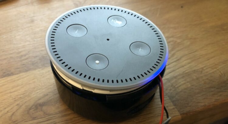
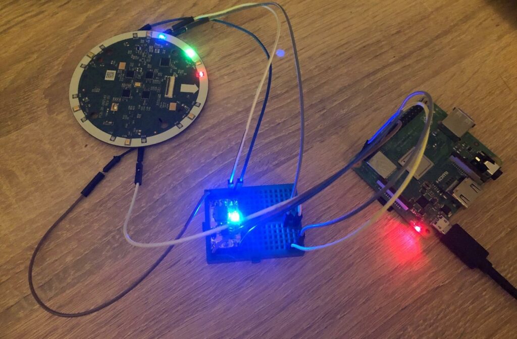
What a time to be alive! Smart stuff everywhere. Your television, the light, temperature – every day the amount of „smart“ things increases. First they were controlled with buttons. Nowadays you can use an app for almost everything. The next step? Of course – your voice. Every „big player“ has its own voice assistant. The problem of all those assistants is, that they claim to require internet to work. Thanks to companies like Snips you can show that this is not true as the whole recognition and most of the actions work without any internet at all. I build an offline smart speaker with a Raspberry Pi 3 A+ and Respeaker 4Mic-Array which is working really nice. The only problem in this setup is the super-low WAF 😄.
Digg inside Echo Dot
According to statistics, Amazon has a market share of over 50%. The designers from amazon did an amazing job – high WAF, appreciated. You can buy an echo dot, which is a tiny box. Depending on its generation it has several microphones, LEDs, buttons, a speaker and rotation input. I was able to get some cheap „broken“ 2nd gen dots. Thanks to several teardowns the main parts are already well known:
- IS31FL3236 (36 Channel PWM Driver, I²C)
- TLV320ADC3101 (2 Channel Audio Input, I²C + I²S)
- TLV320DAC3203 (Audio Output, I²C + I²S)
There are some unknown ICs, but let’s ignore them for now. I searched for a GND pin and measured every testpoint on the top board which holds the microphones and LEDs. The bottom mainboard uses a DAC to connect to a speaker. Let’s skip them for now, too. This is what I found on the top board:
| Test point | Voltage | IC | Pin | Notes |
| TM01 | 1.5V | 0V while minus-button pressed | ||
| TM02 | 1.8V | 0V while plus-button pressed | ||
| TM03 | 1.8V | |||
| TM04 | 3.3V | |||
| TM05 | 3.3V | IS31FL3236 | 36 | SDB (Enable) of LED Controller |
| TM06 | * | * | * | I²C SDA |
| TM07 | * | * | * | I²C SCL |
| TM08 | * | TLV320ADC3101 | 2 | I²S WCLK |
| TM09 | * | TLV320ADC3101 | 1 | I²S BCLK |
| TM10 | * | TLV320ADC3101 | 3 | I²S DOUT |
| TM11 | 3.3V | TLV320ADC3101 | 22 | IOVCC |
| TM12 | 3.3V | |||
| TM13 | 1.8V | TLV320ADC3101 | 23 | DVCC |
| TM14 | 1.8V | |||
| TM15 | 3.3V | |||
| TM16 | 3.3V | TLV320ADC3101 | 38 | AVCC (+LEDs) |
| TM17 | GND | |||
| TM18 | GND | |||
| TM19 | GND | |||
| TM20 | GND | |||
| TM21 | GND | |||
| TM22 | GND | |||
| TM23 | 1.8V | TLV320ADC3101 | 4 | RST |
| TM24 | * | Bus / Microphone? | ||
| TM25 | GND | |||
| TM26 | GND | 3.3V when microphone „disabled“ | ||
| TM27 | 3.3V | 2.3V when microphone „disabled“ | ||
| TM28 | 3.3V | 2.3V when microphone „disabled“ | ||
| TM32 | GND | |||
| TM33 | 1.5V | 0V when minus-button pressed | ||
| TM34 | 1.8V | 0V when plus-button pressed | ||
| TM35 | 1.8V | 0V while circle-button pressed | ||
| TM36 | 2.3V | |||
| TM37 | 1.8V | |||
| TM38 | 1.5V | |||
| TM39 | 2.3V | |||
| TM40 | 1.8V | |||
| TM41 | 1.5V | |||
| TM42 | 1.8V | |||
| TM43 | 2.3V | |||
| TM44 | 1.5V | |||
| TM45 | * | Bus / Microphone? | ||
| TM46 | 2.3V | |||
| TM47 | 1.8V | |||
| TM48 | 2.3V | |||
| TM49 | 1.5V | |||
| TM50 | 1.8V | |||
| TM51 | 1.5V | |||
| TM52 | 1.8V | |||
| TM53 | 2.3V | |||
| TM54 | 1.5V | |||
| TM55 | 2.3V | |||
| TM56 | 1.8V | |||
| TM57 | 2.3V | |||
| TM58 | 1.5V | |||
| TM59 | 1.8V | |||
| TM60 | 1.5V | |||
| TM61 | 1.8V | |||
| TM62 | 2.3V | |||
| TM63 | 1.5V | |||
| TM64 | 2.3V | |||
| TM65 | 1.8V | |||
| TM66 | 2.3V | |||
| TM67 | * | Bus / Microphone? | ||
| TM68 | 1.8V | |||
| TM69 | * | Bus / Microphone? | ||
| TM70 | 1.8V | |||
| TM71 | 2.3V |
Raspberry Pi everything
Amazon is really kind to us – the I²C-Bus talks with 3.3V. Let’s plug 3.3V, GND, SDA and SCL and check, what a bus scan gives us with:
i2cdetct -y 1
| 0 | 1 | 2 | 3 | 4 | 5 | 6 | 7 | 8 | 9 | A | B | C | D | E | F | |
| 00 | — | — | — | — | — | — | — | — | — | — | — | — | — | — | — | — |
| 10 | — | — | — | — | — | — | — | — | 18 | 19 | 1A | 1B | — | — | — | — |
| 20 | — | — | — | — | — | — | — | — | — | — | — | — | — | — | — | — |
| 30 | — | — | — | — | — | — | — | — | — | — | — | — | — | — | — | 3F |
| 40 | — | — | — | — | — | — | — | — | — | — | — | — | — | — | — | — |
| 50 | — | — | — | — | — | — | — | — | — | — | — | — | — | — | — | — |
| 60 | — | — | — | — | — | — | — | — | — | — | — | — | — | — | — | — |
| 70 | — | — | — | — | — | — | — | — |
Uh, nice. Five devices. According to the datasheets 0x18 – 0x1B are the four ADCs of the microphones and 0x3F is the LED controller. That was easy! Let’s check the datasheet and send some data to the LED controller. Sadly no luck. After some research of the datasheet I had to enable the controller by setting 3.3V to the SDB pin. Why does the chip respond via I²C when it is not enabled? 😠 After adding 3.3V to the PIN, I really was able to control the LEDs of my Echo Dot.
Also I used a MAX98357 I²C sound card with integrated amplifier. Since the Dot exposes its speaker pins within the case, the access was really easy. I can listen to music via my Dot. Only the microphones are missing. The ADCs have to be powered with 1.8V – where I don’t have capable supply. I ordered one and have to wait for them. After that I’ll try to access the microphones. Maybe I can really use them with Snips. We’ll see.
Or – even better – did anyone ever do this? The only results I get searching for this is how to install Alexa on your raspberry pi…


Hello, Sascha! Thank you for figuring out purpose of most of the test points. This was very helpful in my project where I add a hardware mute function using an external microcontroller. You can check that out here: https://youtu.be/OSyf_FsDwfk
Hi
interesting approach! I followed a different plan and reached a quite high WAF 🙂 See the hackaday post about it:
https://hackaday.com/2021/03/22/amazon-echo-gets-open-source-brain-transplant
And I have such a Echo Dot laying around doing nothing, sadly nobody has a good hack for it yet AFAICT…
How did your follow-up adventure with the microphones end?
I saw this post and am watching XDA for CFW. Sadly Sonos aquired Snips and „just closed“ them without further notice. After that I did not find time for more investigation. At least I can tell that a Pi Zero fits into an Echo Dot and is (was) capable to run Snips voice recognition. At least with Snips you could also just use the device to record the voice and let the parsing happen on a more powerful device. If my time allows, I want to check out https://github.com/rhasspy/rhasspy as an alternative to Snips.
I also had the idea with the Pi Zero and researched a bit, it seems it is totally capable of I2S (and of I2C of course), which should be enough to talk to the upper board, including LEDs, microphones and buttons (with some GPIOs maybe).
On the other hand you end up with 4 buttons, a LED ring and _7 microphones_ in the Linux system of your Pi Zero… I doubt it is powerful enough to run ODAS and you might want to avoid streaming 7 audio channels through your network.
So my next idea would be to increase the height of the Dot to fit a Raspberry Pi 4 _vertically_, which should have enough processing power. Either 3D-print a housing for that or use a soup can xD
I’d love to work on it, but I’m afraid that won’t happen anytime soon
Thanks for this article, its very helpful!
Any updates on microphone connection?
Hi Timur,
thank you for your comment. Sadly, I just received required parts, but had so much to do… Can’t tell when this will get better
I know that it has been a while but thank you for starting this effort.
I am going to begin work on this effort and was wondering if you have had any opportunity to get further along with your efforts.
I am also aware that snips was sold to Sonos but I believe I have another solution that will work form a software standpoint if I can get the hardware working.
Until today, I did not find time to dig into this topic again . Hope to find some time for projects in April.
Hi, was wondering if you ever had any luck getting the microphone array to work, and if so if you could add some steps? If not, what did you wind up purchasing to power the ADCs @ 1.8v?
Still no luck on my site the parts are here, but time is missing. If I manage to do some more tests, I’ll definitely write another post!